Astable 555 Circuit Diagram
555 timer basics Astable circuits 555 timer ic flasher astable circuit led simple diagram circuits seekic ne555 basic leds light full gr next
555 Timer Basics - Astable Mode
555 timer basics Introducing 555 timer ic 555 timer basics
555 astable circuit diagram timer multivibrator circuits calculator using electronic mode led time off formulas cycle full
Solved: chapter 6 problem 20p solutionAstable 555 timer schematic Metronome using astable mode of 555 timer ic555 timer astable multivibrator using ic working.
555 timer circuit ic diagram astable mode tutorial introducing555 astable circuits circuit 1khz multivibrator operation volts Ready to help: astable multivibrator using ic 555555 astable timer multivibrator circuit using diagram ic mode circuitstoday.

Best of 555 timer application circuits explained
555 timer led astable mode flashing circuit blinking potentiometer using resistor photoresistor capacitor light basics flash circuitbasics diagram make ohmAstable multivibrator using 555 timer Astable multivibrator using 555 timer555 timer led astable mode flashing circuit blinking using resistor potentiometer capacitor light photoresistor basics circuitbasics flash diagram make when.
Astable multivibrator using a 555 timer ic workingAstable circuit 555 led gif off detail repeated completely pulses switched until because three power technologystudent elec1 555 astable timer circuit multivibrator diagram using oscillator diode circuits voltage regulator input555 astable circuit ic multivibrator timer using pulse generator diagram light help circuits sensor audio make connect pc here chip.
555 astable circuit circuits timer lm ic mode multivibrator explained diagram monostable using simple application tracking infrared system ir operation
555 timer astable oscillator circuit555 astable timer circuit instructables tutorial lm555 datasheet discharge 555 timer led astable mode flashing circuit blinking potentiometer using resistor capacitor photoresistor light basics flash circuitbasics diagram make ohmAstable 555 circuit circuits oscillator electronics.
Astable 555 timer ic flasher circuit diagramWhy does this 555 timer not work correctly when i plug in the z80 cpu 555 timer astable multivibrator circuit diagram555 astable timer mode circuit pwm duty cycle control voltage using variable schematic resistor output step lab public input make.

The 555 astable circuit
555 astable timer circuit multivibrator diagram mode ic circuits pulse operation using clock trigger electronics circuitdigest timers generated projects electronic555 astable metronome Astable 555 configuration resistor external circuit timer oscillator figure r1 diagram‘555’ astable circuits.
555 timer astable multivibrator circuit diagram555 astable circuit timer schematic calculator works using tools allaboutcircuits disconnect jumper touch only when overview .


555 Timer Astable Multivibrator Circuit Diagram

‘555’ Astable Circuits | Nuts & Volts Magazine

555 Timer Basics - Astable Mode

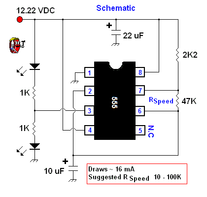
Astable 555 Timer Schematic

555 Timer Basics - Astable Mode

Why does this 555 timer not work correctly when I plug in the Z80 CPU

555 Timer Astable Multivibrator Circuit Diagram

555 Timer Basics - Astable Mode